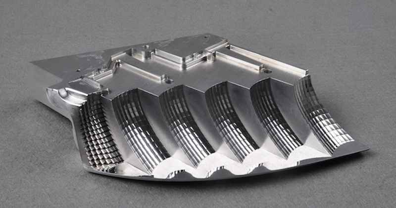
Custom Mold and Die Making with High-Precision Milling

In mold and die work, precision milling directly affects your part’s function and the fit. Usually, tight features like shut-offs or ejector slots must be carefully milled within ±3 μm. Such accuracy depends on toolpath control, cutting stability, and minimal runout, generally no more than 0.002 mm.
In multi-cavity dies, even small shifts can negatively affect part symmetry. So, you must calibrate your spindle speed and fixture expansion per cycle. 5-axis machining setups can cut complex undercuts, but tool length errors still impact alignment. This isn’t textbook geometry; so, you need a practical control of burrs, surface isotropy, and wear-critical edges.
In this article, we will discuss effective tips for high precision CNC milling for custom profiles and narrow designs.
Toolpath Programming for Sharp Edges and Tight Radii
Mold geometry with sharp corners is never lenient. You don’t merely control tool movement, but also need to guard shutoff integrity. An early braking during a corner with a radius of 0.3mm will blunt the edge and lead to bounce-back. Cutter must perform under high pressure and wear to ensure proper sealing.
For steel like H13 or D2, the tool should exit before cutting tight areas. This implies arc-lead entries, pre-ramping, and tapered transitions. The CAM defaults are usually slow to respond: the tool is already overcut. To avoid the motion lag on micro-radii arcs, you need to linearise corners manually in the tool path.
Micro features, particularly in lifter seats or ejector holes, require rest-mill passes at the actual insert blend radius. Do not apply generic pencil paths. Instead, use a stepover of less than 10% of the tool diameter. Tool length also has to be less than 3xD. Otherwise, your part can be prone to axial whip. That is where edge rounding lurks, not in feed rates.
In precision machining, milling corners isn’t just about cutting speed or depth. The way the tool enters and exits also plays a vital part. A corner needs to be cleared and not gouged. Your direction should steadily go up, away, and back without reloading the edge.
Tooling and Coating Choices for Hardened Die Steels
Cutting 48–56 HRC steel demands managing heat, tool pressure, and part stability. These steels can not handle violent insertion and heat spikes. Therefore, tooling needs to be optimized enough to reduce deflection, prevent heat in the cutting area, and have edge integrity after long uninterrupted runs. At the stage of completing passes, there is no space to make mistakes.
A bad tooling translates to a ripple effect throughout the whole die assembly. A single chipped tool will move a shutoff face and change in electrode geometry. This will further require manual rework. So, you need to deploy cutters that retain their edge when under prolonged load and coatings, and do not peel off halfway through a steel core. Precision dies need uniform control of all the contacts between the tool and the job piece.
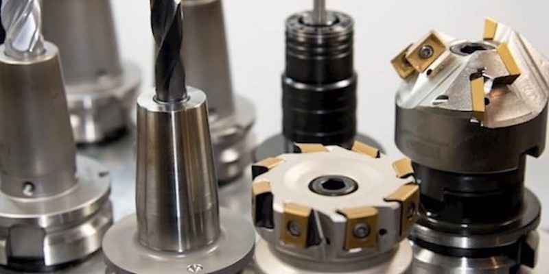
Cutter Design
Choose cutters with reinforced cores and variable helix geometry. Keep the projection short. This allows you to limit axial flex in deep pockets. Moreover, avoid sharp corners and use small corner radii to control stress.
Coating Type
Use AlTiN or TiSiN for high-heat dry cuts in tool steels. Further, match the coating to the actual tool speed, chip load, and coolant use. Avoid decorative coatings to eliminate the risk of cracks under thermal cycling.
Tool Life Planning
Use roughing and finishing tools, even with the same specs. Track tool usage by engagement zone, not cycle count. Update offsets as tools wear, and do not rely on visual checks only.
Managing Thermal Expansion in Multi-Pass Cavity Milling
In deep cavity milling, heat builds up in both the tool and the steel. This causes the material to expand slightly as it undergoes a long cycle of machining. Without considering that, there is a possibility that your part may move a few microns. This influences the ultimate depth and wall placement. It is observed by uneven floor height and a gap in the shutoff areas after mold assembly.
To avoid this issue, it is useful to interrupt long passes and give short cooling intermissions between roughing and finishing. Maintaining a steady coolant flow that is directed straight at the tool tip also helps in minimizing heat in confined areas. Moreover, you can stagger cutting paths to spread heat evenly in the cavity. The expansion control is not such a complicated setting. It is just watching the flow of heat and changing your order to make the part constant.
Your reference points may also change with time due to thermal shift. If you probe, then cut without checking expansion, your zero point changes. This is a problem in final passes, particularly where cutter paths depend on steady stock as left by roughing. This can be simply dealt with by re-probing critical areas after the roughing or by implementing mid-process verification routines. In that way, you can detect the movement before it leads to a mismatch in such critical details as lifter slots and ejector pockets.
In-Process Metrology for High-Tolerance Mold Features
For keeping ±5 μm tolerances, early correction remains important. In-process metrology allows you to detect surface and position variations before final passes. Touch probes mounted on spindles measure Z-depths to within ±2 μm. You get real feedback after finishing with roughing. You are able to verify if the material is left evenly, or whether heat and tool wear have changed geometry.
In the case of holes, pockets, or mating features, X and Y accuracy is equally important. Probing routines applied to semi-finished parts assist in identifying the lateral position changes due to tool deflection and fixturing error. Probes with high resolution can measure between +/-1.5 microns in the plane. This will allow your ejector sleeves, guide pins, or lifter parts to fit without manual spotting and adjustment.
Another issue in long cavity runs is thermal expansion. The internal heat in steel blocks normally thicker than 100mm may move the Z-axis by 6-8 micrometers over time. Re-probing reference datums, such as corner bosses or dowel bores, before finishing also aids in restoring true part position. This correction is directly returned to your machine control, updating tool offsets, and changing the cutter entry depth without interrupting the cycle.
Conclusion
High-precision mold and die making relies on optimum control at every stage of machining. Whether it is sharp corners or hardened steel cavities, consider the tool geometry, coatings, and toolpaths strategies. When it comes to long, multi-pass jobs, heat accumulation and tool wear are equally critical as the tightness of tolerance is.
These are all linked through in-process metrology. When you inspect surfaces and features during machining and not later, small errors tend not to become major issues. Probing, heat control, and smart cutting keep each cavity accurate, consistent, and ready to use without rewrok.